

Hey there! As a supplier of Single Phase Output VFDs, I often get asked about harmonic distortion. So, I thought I'd take a moment to break it down for you.
What is Harmonic Distortion?
First off, let's talk about what harmonic distortion actually is. In simple terms, when we're dealing with electrical systems, the ideal voltage and current waveforms are pure sine waves. But in reality, the waveforms we get can be a bit messed up. Harmonic distortion is the deviation of these waveforms from the perfect sine - wave shape.
When we use a Single Phase Output VFD, the process of converting the input power to the desired output frequency and voltage can introduce these non - sinusoidal components. These non - sinusoidal components are called harmonics. They are integer multiples of the fundamental frequency. For example, if the fundamental frequency is 50Hz, the 2nd harmonic will be 100Hz, the 3rd harmonic will be 150Hz, and so on.
Why Does Harmonic Distortion Matter in a Single Phase Output VFD?
Now, you might be wondering why harmonic distortion is such a big deal. Well, it can cause a whole bunch of problems.

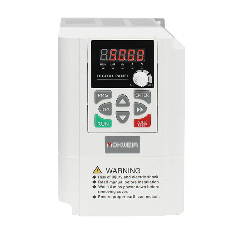
Equipment Damage
One of the major issues is equipment damage. Harmonics can cause overheating in motors, transformers, and other electrical equipment. The extra heat generated by the harmonic currents can reduce the lifespan of these components. For instance, a motor that is exposed to high levels of harmonic distortion may experience premature insulation breakdown, leading to costly repairs or replacements.
Power Loss
Harmonic distortion also leads to power loss. The non - sinusoidal currents and voltages increase the effective resistance in the electrical system. This means that more power is dissipated as heat, rather than being used productively. As a result, your energy bills can go up, and the overall efficiency of your system drops.
Interference
Another problem is interference. Harmonics can cause electromagnetic interference (EMI) with other electrical devices. This can lead to malfunctions in sensitive equipment such as computers, communication systems, and control devices. You might experience data loss, communication errors, or even complete system failures.
How Does a Single Phase Output VFD Cause Harmonic Distortion?
A Single Phase Output VFD works by taking the input power and converting it to an output with a variable frequency and voltage. The conversion process typically involves rectification and inversion.
During the rectification stage, the AC input is converted to DC. This is usually done using diodes or thyristors. The non - linear nature of these components causes the input current to be non - sinusoidal, introducing harmonics.
In the inversion stage, the DC is converted back to AC at the desired frequency. The switching action of the power transistors in the inverter also generates harmonics. The way the VFD is designed, the modulation techniques used, and the quality of the components can all affect the level of harmonic distortion.
Measuring Harmonic Distortion
To understand the level of harmonic distortion in a Single Phase Output VFD, we use a parameter called Total Harmonic Distortion (THD). THD is expressed as a percentage and represents the ratio of the root - mean - square (RMS) value of all the harmonic components to the RMS value of the fundamental component.
Most modern power analyzers can measure THD easily. By measuring the THD of the voltage and current, we can get an idea of how much distortion is present in the system. A lower THD value indicates a cleaner, more sinusoidal waveform and less harmonic distortion.
Reducing Harmonic Distortion in a Single Phase Output VFD
There are several ways to reduce harmonic distortion in a Single Phase Output VFD.
Filters
One of the most common methods is to use filters. Line reactors and harmonic filters can be installed between the VFD and the power source. These filters help to smooth out the current waveform and reduce the harmonic content. For example, a line reactor can limit the rate of change of current, which in turn reduces the high - frequency harmonics.
Advanced Control Algorithms
Some VFDs use advanced control algorithms to reduce harmonic distortion. These algorithms can adjust the switching pattern of the inverter to minimize the generation of harmonics. By carefully controlling the timing and amplitude of the switching pulses, the VFD can produce a more sinusoidal output waveform.
Multi - Pulse Rectifiers
Another option is to use multi - pulse rectifiers. Instead of a standard 6 - pulse rectifier, a 12 - pulse or 18 - pulse rectifier can be used. These multi - pulse rectifiers have a lower harmonic content because they use more diodes or thyristors in the rectification process.
Our Single Phase Output VFDs
As a supplier of Single Phase Output VFDs, we understand the importance of minimizing harmonic distortion. Our VFDs are designed with state - of - the - art technology to reduce the level of harmonics. We use high - quality components and advanced control algorithms to ensure a clean and efficient output.
If you're in the market for a Single Phase Output VFD, we've got you covered. Our products are not only reliable but also offer excellent performance. We also have Single Phase Input 3 Phase Output VFDs and 220v To 380v VFDs that can meet a variety of your power conversion needs.
Contact Us for Purchase
If you're interested in learning more about our products or want to discuss your specific requirements, don't hesitate to reach out. We're here to help you find the right VFD for your application. Whether you're looking to reduce energy costs, improve equipment performance, or simply need a reliable power conversion solution, we've got the expertise and the products to make it happen.
References
- Electric Machinery Fundamentals, Stephen J. Chapman
- Power Electronics: Converters, Applications, and Design, Mohan, Undeland, and Robbins